To the contrary then most people believe, Revit Architecture can actually do complex shape as the Revit core engine can actually handles complex geometries. It is only that the current geometric tools are currently a bit limiting even though Revit Architecture 2009 Swept Blend function proves a great improvement.
 The left is one of the illustration courtesy of Craig Barbier.

I
was looking around for a way to create lattice look fence and come across this article in HOK CAD Solutions. So this save my time in writing a new one about it. Enjoy! Darryn B, LON asks: I need to create a timber lattice structure, such as the attached pictures, as a wall and possibly as a slab too. I was wondering if anyone knew of or has done anything like this before?
 William LC responds: Here’s a couple of examples on the approach I would take for a Timber Lattice Material.As you can see I’ve played with Transparency and Bump, for a straight and a 45º option. You can use it in a Wall or in a Curtain Wall setting (my recommendation), be careful to modify the Mullions accordingly too.
  In my test the Lattice is roughly 8 cm wood x 12 void, but that can be customized through the Maps and Map Alignment. Notice the material has a 50% Transparency and a Surface Pattern, for Revit shaded or Hidden views.
There are quite a number of standard family template for us to create families of different categories. However, are you able to create your own family template? The answer is - it is possible.
1. You may copy an existing family template say Generic Model. Rename it Custom Template.
2. Now this is the trick. Rename the template from .RFT to .RFA. This will allow you to edit the template file.
3. Customize your template file as required. Saved it and rename it back to .RFT.
4. Now when you create a new family, there will be a new template call Custom Template.
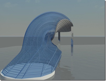
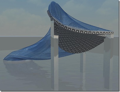
I was checking out the blog by David Light. He and a couple of other bloggers are pushing the limits of Revit curtain wall panel. So I was trying to follow what he has done with the curtain wall panel to create some custom curtain wall which is sculpture like.The following picture is the results of such experimenting: If any of the readers is interested to know how this is being done. Please check out the blog by David Light or email me for further information. Basically I am just creating two Generic Models and load them into a custom curtain wall panel.